

Spherical Quadruped Arduino Robot : 10 Steps (with Pictures) - cervantezarrierld
Introduction: Round shape Quadruped Arduino Automaton
Welcome,
Two years ago, by curiosity, I ordered an Arduino starter kit without background knowledge connected electronic and code. I do non make out what happened to ME...
I battled during the first two weeks to just blink a led....
Weeks and months after, projects after projects, the pleasure to trifle with Arduino did not dissolve, quite the contrary.
I successful tangible progress using internet publications, now it is time for ME to share my own experience.
I am pleased to present my first Instructable.
The existing Instructable describes a spherical quadrupedal robot. The dishonorable of the golem is a quadruped platform with two articulations by leg and all integrated into a spherical frame. Connected standby mode, the robot looks like a sphere and transforms itself into quadruped to go up. An ultrasonic sensing element is accustomed avoid clangour during motion.
- Weight unit : 440 g
- Dimensions : Ø 130 millimeter / 5.12 in
- Running Clip (battery life) : 15 Min
- Programming Language : Arduino C/C++
Step 1: Parts List
Electronics :
- 1 x Arduino Nano
- 1 x Servo Driver : Adafruit 16-Transmission channel 12-bit PWM
- 10 x Reactionary Angle Male Head
- 10 x Servomotor : Magnolia State-12016
- 1 x NIMH stamp battery pack : 4.8v - 1800 mAh
- 1 x Ultrasonic sensor : SRF05
- 4 x NeoPixel : Adafruit breadboard-friendly RGB Smart NeoPixel
- 1x 470 ohm resistance (for NeoPixel)
Mechanical Parts :
- 18 x Individual-tapping Phillips chicane : Ø1x6 - (Servo Arm vs Structure Parts)
- 10 x Standard screw (Servo Arm vs Servomotor)
- 17 x Self-tapping Phillips screw : Ø1.6x6 - (Structures fixation)
- 2 x Individual-tapping Phillips screw : Ø2x8 - (Ultrasonic Sensor arrested development)
- 20 x Head screw DIN 84 : Ø2x10 - (Servomotors regression)
- 5 x Self-tapping Philips get it on : Ø2x8 - (Electronic boards fixation)
- 4 x Anti-slip footslog
- 4 x Cable clamp
3D Model :
Entirely the composition parts were designed for 3D printing.
Download the files from Thingiverse
Step 2: Doors
Functionality :
The doors shroud the legs when in retracted position as well as the free space area for the legs motion. So when the automaton is in standby manner with the doors obstructed, it looks like a sphere.
Precept :
All the doors are piloted by one servomotor placed in central lay out. The doors are actuated aside means of an extension cross. The doors are guided with two pins engaged in rails on the body. The track impose a double motion to the door, ane for retracting inside the consistency and a second one for turning it.
The servomotor speed is too fast leading to sudden movement, the speed is reduced by means of loop with delays on the code.
Step 3: Legs
Functionality :
Obviously the legs are used for walk but they moldiness also permit to raise & get down the robot.
The legs must equal covert in understudy mode.
Principle :
- Design
There are several manageable concepts for the legs. Due to little space available in the retracted domain (Inside the consistence) the solution with 2 servomotors by leg was preferred. One for the smart &adenosine monophosphate; backward motions and one for the up & down motions.
To redress for the missing fractional servomotor (the "classic" quadruped has three control system per leg, Hip, Knee, Ankle) and to ensure the lifting motion of the robot without legs sliding, a parallelogram kinematic motion was added to the up & down servomotors i.e. two functionalities with one servomotor, the ascending & down motion and the legs parallelism.
In order to optimize the space, the tibia structure is part of the head shape in retracted post.
- Lepton
Cardinal servomotors per leg and 4 legs mean 8 servomotors, plus one for the head and one for the doors = 10 servomotors. To minimize the number of Arduino board pins used & cables, the servomotors are pressurised by a servo device driver with I2c interface i.e. only deuce pins exploited.
Tutorial along the Adafruit Servo Device driver
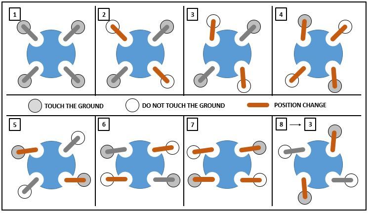
- Manner of walking
At that place are several walking patterns, one leg afterward another, two opponent legs at the same time, four legs simultaneously and several parameters like the motion bountifulness & the movement cannonball along. Conclusion : many possibilities.
This Instructable describes solely one solution (it is up to you to explore others), two diametric legs at the same time. The walking diagram can be seen below.

The legs motion are non complex, there are no transformation matrices. Continual variables impose the position of all servomotors.
Special tending must follow cashed to the legs sliding essence, good detrition between the legs and the ground is essential to ascertain a regular walking. To minimize this phenomenon few opposed-slip pads were added connected legs bases.
Ill-use 4: Head
Functionality :
The head supports the ultrasonic sensor and allow its rotation systematic to enlarge the review partition.
The lead is also the automaton lid. The head is easily removable and give access to the electronics, Arduino connections & barrage recharging.
Principle :
The shape of the servo arm is replicated on the head, so it is only embedded on it with a borderline breach. The head turns concurrently as the servomotor. Just lift it to consecrate access to the electronics.
The ultrasonic sensing element is connected aside agency of JR connectors to the Arduino board to ease the disassembly.
Again, to annul a sudden movement of the servomotor, a delay loop is added in the code to slow down the revolution.
Stride 5: Lights
Functionality :
That clearly is non an must functionality so this is wherefore it is vital. Lights simply mean more diverting.
Principle :
4 RGB leds are equally spaced complete around the body. The lights are visible between the gap of the bottom fixed region and the top rotating part (foreland). The RGB leds provide to create any light animations away color changing Oregon blinking during the robot events.
Tutorial on the Adafruit NeoPixels
Stone's throw 6: Ultrasonic Sensor
Functionality :
The ultrasonic sensing element is used to check if in that location is an obstacle in front of the robot and to avoid it.
The sensor is as wel utilised arsenic a change to start and stop the golem.
Principle :
- Obstacle Detection
The detector emits an ultrasound which travels through the air and bounces back to the detector if the impressive meets an obstacle. The sensing element provides the go under time of the bespeak. With the point speed (know time value) it is affirmable to calculate the distance to the obstacle.
If an obstruction is heard, the robot stops, turns its head to right side to mensuration the free length and repeats the measurement on the left side. The robot rotates towards the side with the greatest free outstrip.
You can find on the diagram below the automaton legs strategy for the rotation, over again it is only one possibility among many others.
This Instructable does not detail the ultrasonic sensor operation, there are already so many details happening the net.
Tutorial on SRF05 Ultrasonic sensing element
- Transposition
To keep a spherical aspect, in that respect is No physical turn on the robot, so the ultrasonic sensor is used as so much. If an obstacle is detected very draw in front of the sensor, the robot leave originate in or stop.
The ultrasonic sensor do non switch off electrically the robot. To shut off the power you indigence to lift awake the lid (Oral sex) and disconnect the battery.
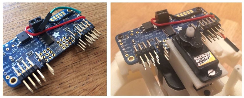
Step 7: Collecting
Nothing complicated, no traps. The pictures speak for themselves.
Minor comments :
- Do non forget to give some slack to the branch servomotor cables, the servomotors mustiness be free to move. Same for the ultrasonic sensor cables.
- Extraordinary cable clamps were added to ensure that all the cables are locked on the focal structure of the automaton and do not shake up the motions.
- Quadrant Male Headers are ill-used with the servosystem motor driver dining table. There is not decent quad purchasable vertically so the connections are orientated horizontally.
- For the legs articulations, the operative gaps are 0.1mm axially & 0.1mm radially. You could obtain these values immediately with the FDM 3D printers. You English hawthorn want to update them contingent your own 3D printing machine performance/truth.
- The structural parts were concentrated unitedly by means of self-tapping screws.

Step 8: Wiring
The servo driver gameboard I2C interface impose to connect the SDA & SCL ports to A4 &adenylic acid; A5 pins connected Arduino Nano. No more constrains.
Otherwise, follow the lines.
Step 9: Beginning Code
The code is structured as a state machine.
The servomotors are piloted with constant variables. All these variables are in the global.h file which must be placed on the unvarying folder than the Spherical Quadruped Robot.ino file.
All the servomotors moldiness be calibrated and the displacement/rotation values must be redefined according to your settings.
Step 10: Conclusion
At project end, on that point are always some satisfying things and some things that could rich person been through with differently. Assessing the pros and cons or the project success is not relevant. The aim is to enjoy yourself patc doing it.
I truly hope this Instructable will inspire you & give you the desire to be creative.
Special thanks to the French Arduino community of interests, the Gallic Arduino blog from Eskimon & the Instructable publications.
Act not pause to contact me if you have some questions.
ENJOY !
1 Person Made This Project!
Recommendations
Source: https://www.instructables.com/Spherical-Quadruped-Arduino-Robot/
Posted by: cervantezarrierld.blogspot.com
0 Response to "Spherical Quadruped Arduino Robot : 10 Steps (with Pictures) - cervantezarrierld"
Post a Comment